

How To Repair Broken Oscilloscope Probe
- Introduction
- Manuals
- Diagnostics and initial checks
- Teardown
- Troubleshooting attempt and 2nd probe repair
- Benchmarks
Introduction
Active probe such as Tektronix TDP1000 rated for providing 1 GHz bandwidth and designed to operate in single-ended or differential way. Information technology have expert high-speed electric and robust mechanical connection for probing. It is current generation probe designed for Tektronix oscilloscopes TekVPI™ probe interface or older TekProbe™ BNC ports.
Feature prepare of this probe:
- 1 GHz analog bandwidth
- less than 1pF differential input capacitance
- one MΩ differential input resistance
- ±42 Five (DC+pk Ac) differential input voltage and input beginning range
- Attenuation x5 or x50
- Noise level <2mV RMS at x5 or <1mV RMS at x50
- Rise fourth dimension <350 ps (for TDP1000/P6251)
- >18 dB CMRR at 250 MHz
- Selectable 100 Hz, 10 kHz, 1 MHz or full BW
- DC reject at 0.4 Hz (x5) or 4 Hz (x50)
I've bought this probe as cleaved/for parts. MSRP for the new Tek TDP1000 is around $4600 USD.
Manuals and service information
TDP0500 & TDP1000 500 MHz & 1 GHz High Voltage Differential Probes Quick Beginning User Transmission
TDP0500 & TDP1000 Loftier Voltage Differential Probes Technical Reference
TDP0500, TDP1000 and P6251 Datasheet
Diagnostics and initial checks
Probe had no physical damage from exterior, did not have any accessory arranged with sale. Later connecting to Tektronix DPO7104 scope probe was correctly recognized and detected.
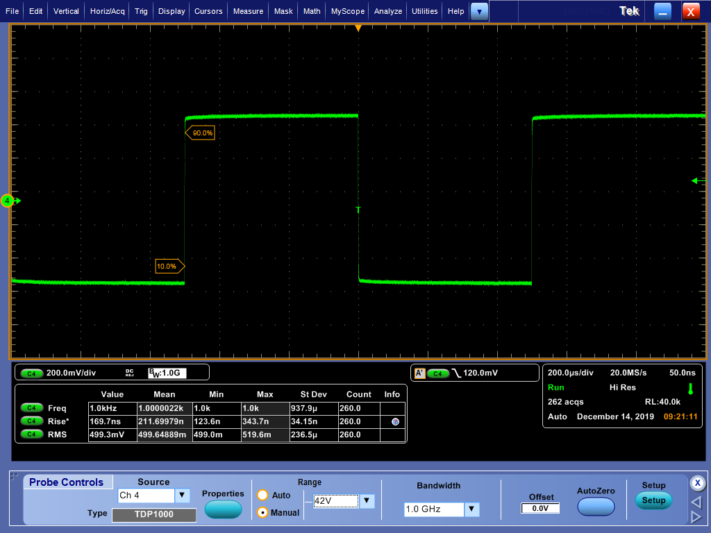
AC square-wave from scope's calibration output showed up on telescopic merely fine.
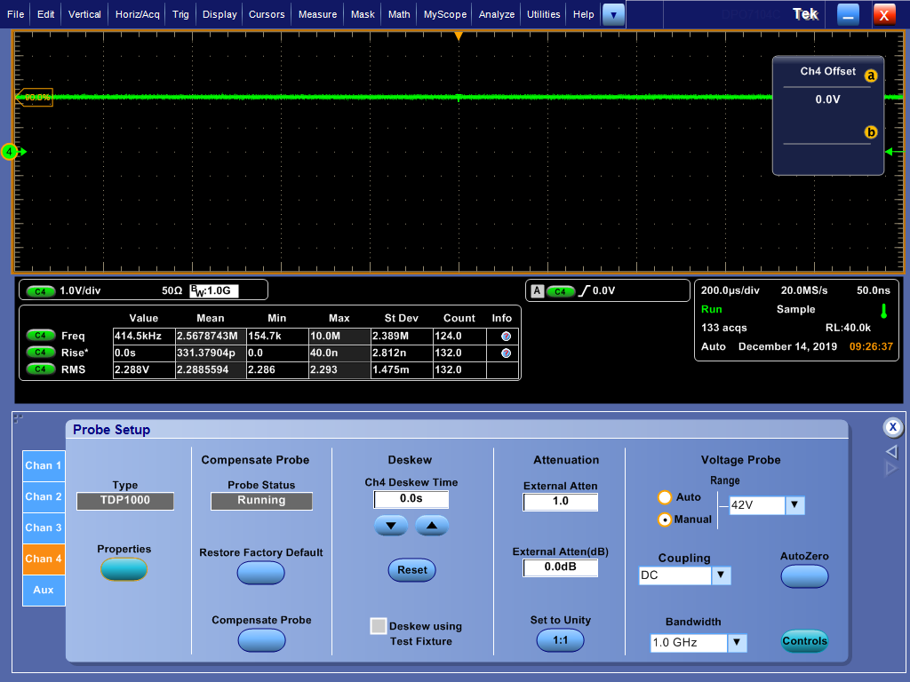
However further testing revealed that probe DC output level clipped high at +2.28 V no matter what settings used.
Both positive and negative inputs were able to laissez passer signals, so it must be something damaged within active amplifier or power supply runway.
Also probe end with all high-speed die-bonded electronics getting really hot after few minutes of functioning. Information technology is normal for active probes to stay warm, but non called-for finger hot.
Teardown
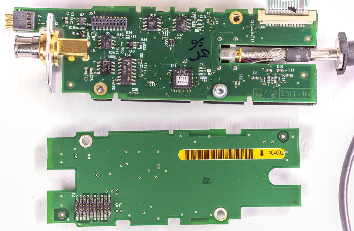
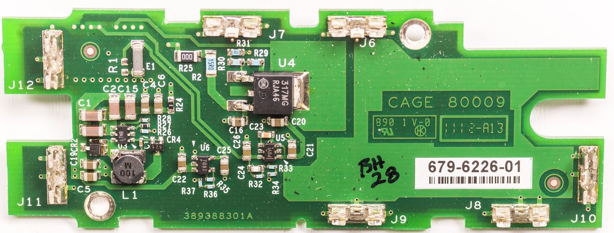
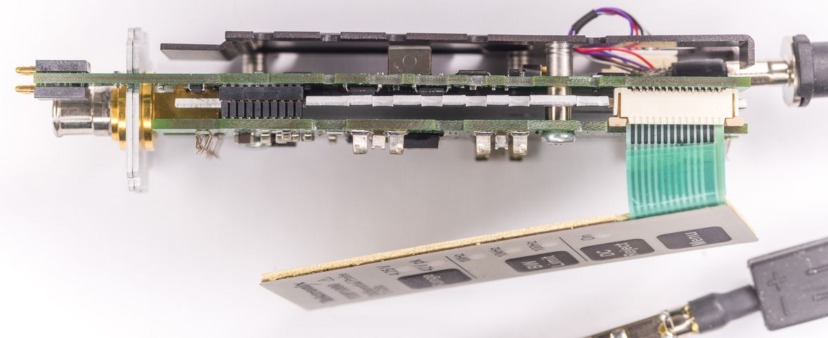
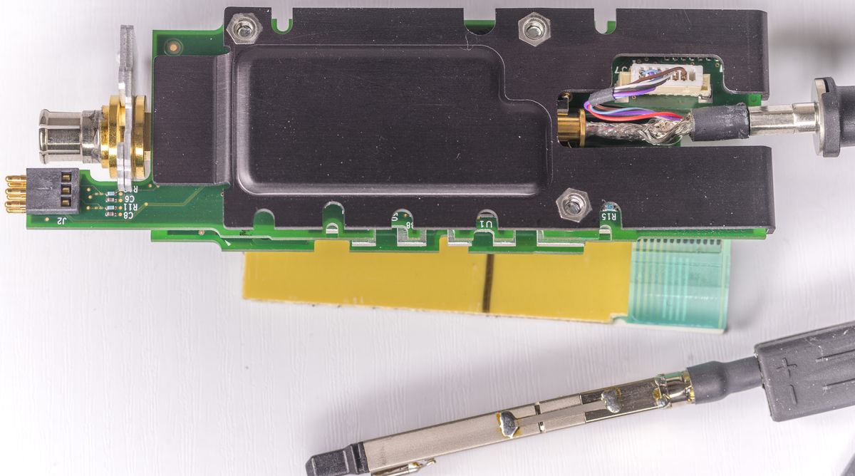
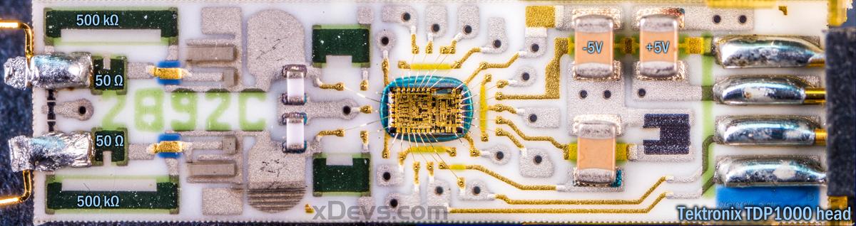
Probe has all auxilary electronics in connector head, that plugs into TekVPI oscilloscope port. In that location are two iv-layer PCBAs, mounted to each other and heatsink shields.
Typical to Tektronix probes, there is little ATMEL ATmega32 eight-bit microcontroller to select various probe functions, provide digital identification for scope, store serial number, etc.
Onboard hardware handle programmable DC start vernier function. It is implemented around BB DAC7612U which is dual-channel 12-scrap fast voltage DAC. There are two dual ultra-depression bias current high gain TI LMC6022 amplifiers
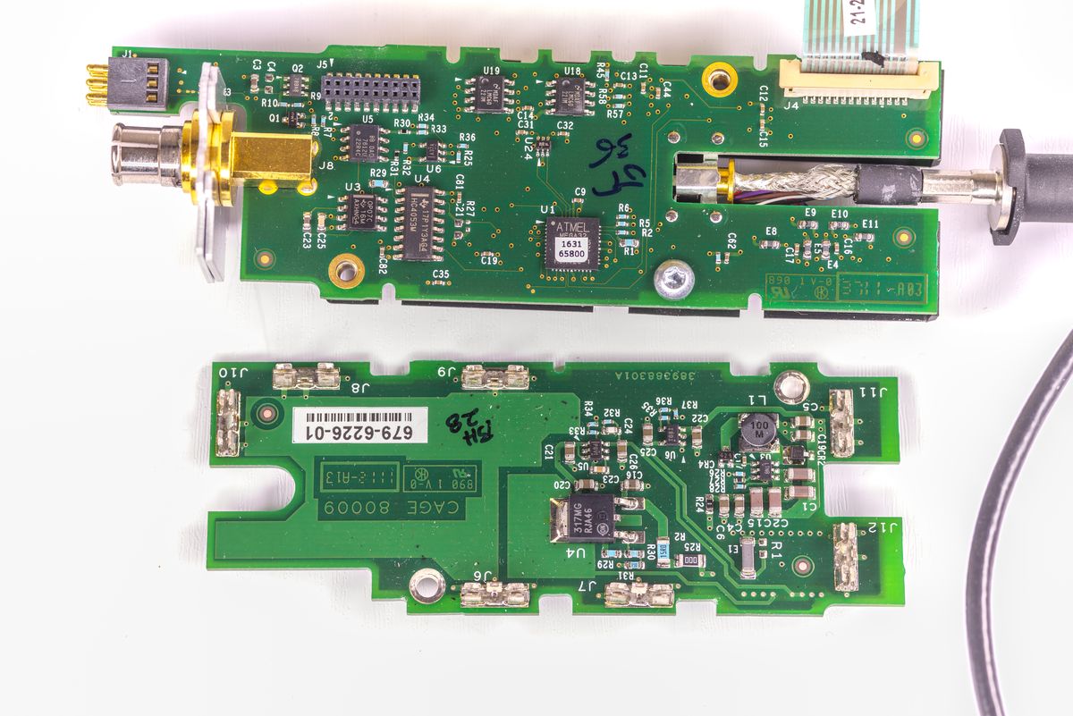
Second board is essentially ability supply to convert input +12V Bulk from telescopic into auxilary runway used past probe electronics. 3 is TPS73001DBV LDO for +5V track, LM317MG in DPAK, TPS732 for negative rail and Linear LT1616 switch-mode supply for +/-15V.
Troubleshooting effort and second probe repair
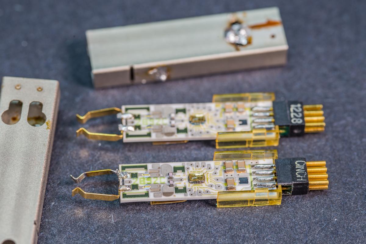
After checking all ability supply rails from probe electronics block further investigation went towards active head. This head is very compact, and usually unrepairable. Fact that head in this bad probe was getting really scorching hot fast was not a good sign.
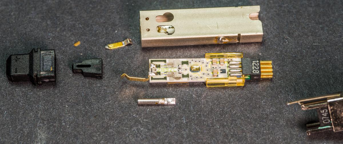
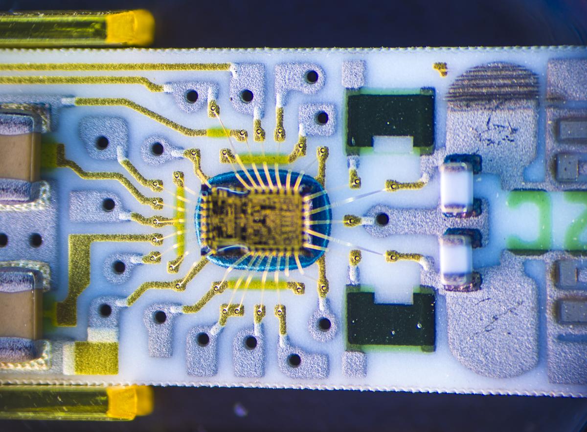
Head was carefully disassembled to go admission for internal circuitry. Every bit suspected it was very specialized bare dice ASIC wirebonded to alumina/ceramic substrate with embedded film resistors and mounted capacitors. There are no easy parts to try replace, and snce I exercise not take replacement custom die nor a wirebonding repair on this head is substantially comes to a dead end.
Even so, some half year after I've purchased second bad TDP1000 in hopes to get one probe out of 2 bad ones. Scope detected 2d probe correctly, but whatsoever signal applied to the input was not displaying. Also both inputs were dead shorted.
Perhaps blown front end ASIC once again? :(
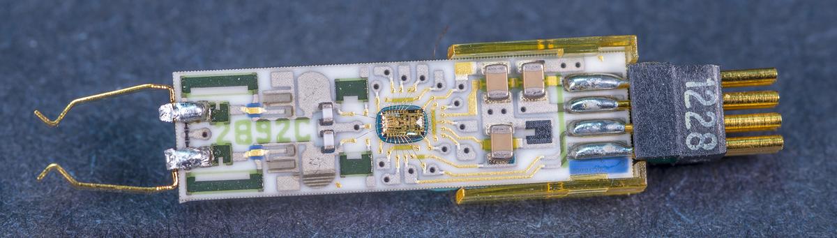
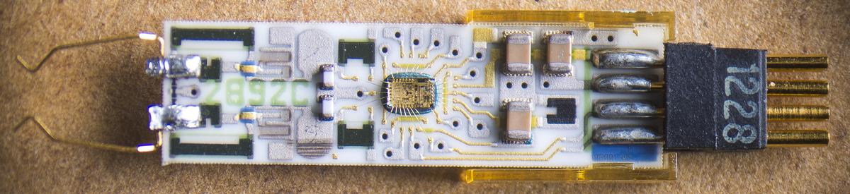
Let's take a footling closer expect on the head electronics.
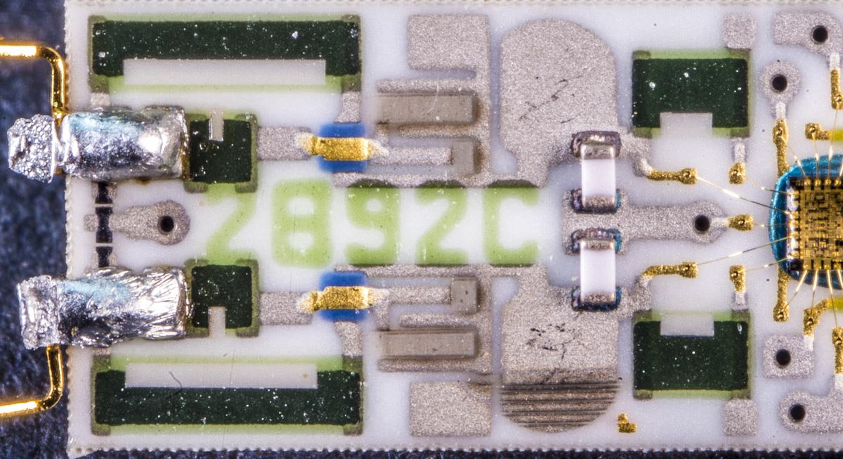
Substrate has marking 2892C, perhaps some internal Tektronix / Maxtec number?
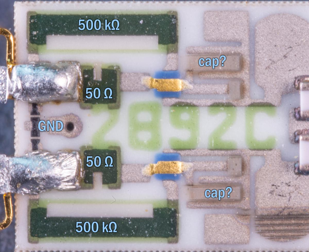
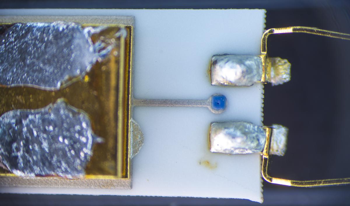
Input springy contacts are soldered to border pad and connected to 50 and 500 kΩ resistor networks, too every bit additional motion picture structures (protection or capacitance trims?).
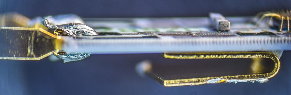
Solid ground connection provided on back side of the ceramic substrate past big U-shaped spring and probe casing. Information technology's all soldered together during probe head assembly.
Lesser side have just film resistors under blue mask, so not much interesting there.
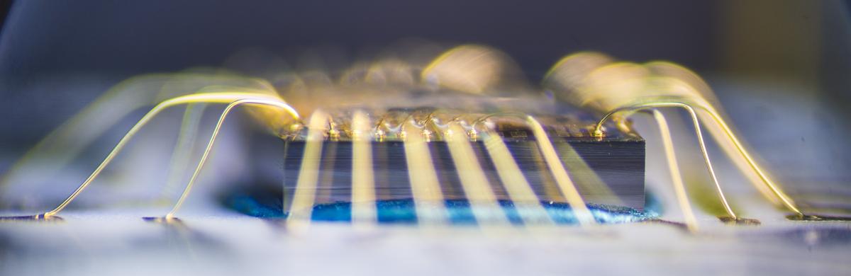
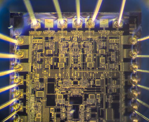
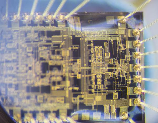
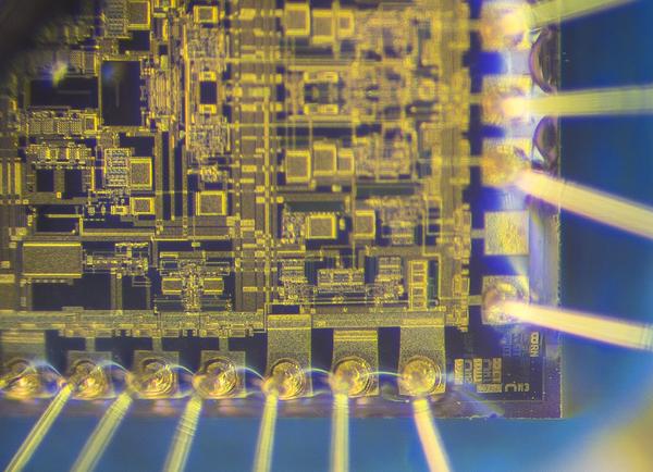
Front side have naked Tektronix M815A (dated 1995) ASIC die with gold wire bond array. There is protective transparent epoxy gel (soft to touch on) on top of die, peradventure for additional protection from dust/humidity? It made photography of the surface structures rather challenging.
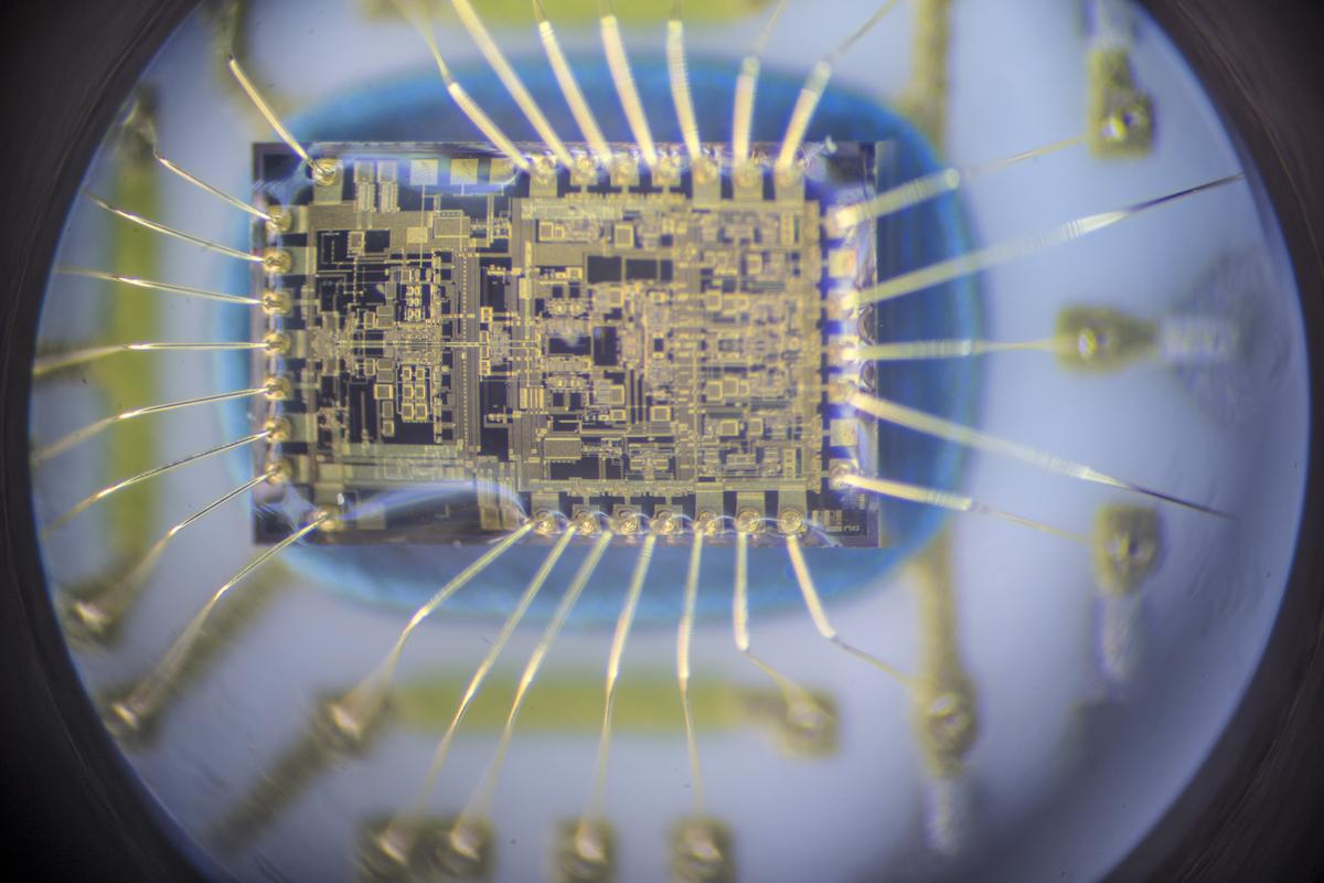
Also photography thru microscope accept extremely narrow focal plane, and then some photos were a stack of multiple sections to get acceptable sharpness.
Result of these attempts shown beneath.
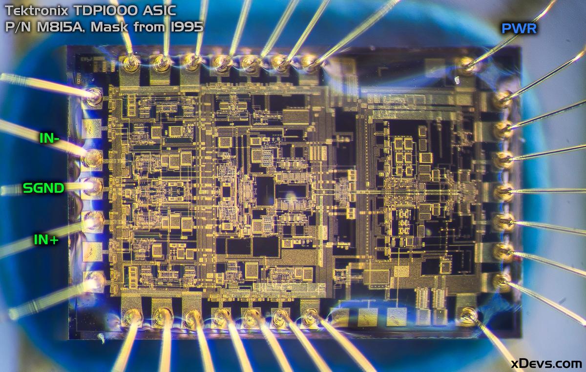
Inputs are on the left side, output most likely on the right side. This die is rather complex having different gain stages and onboard amplifiers to provide wide choice of bandwidths and allow ±42 VDC beginning level programming at the input signals.
![]()
I found that 1 of input bound metallic contacts was somewhat crooked in this probe head and swapped it with some other skilful contact from previous dead TDP1000 head. Checking few voltage levels at the head returned -5.03 VDC and +4.95 VDC levels (on two large caps, third ane was nigh 0 VDC level, possibly some internal offset or bias cap).
Unexpectedly this probe head started working. So information technology was assembled together and TDP1000 passed all self-test and self-calibration procedures!
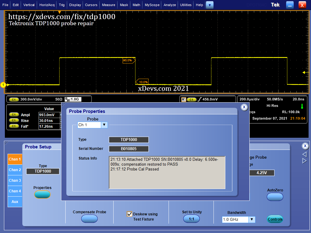
I'll take this every bit a repair success!
Benchmarks and verifications
Some tests were carried out to cheque all ranges and functions of the TDP1000.
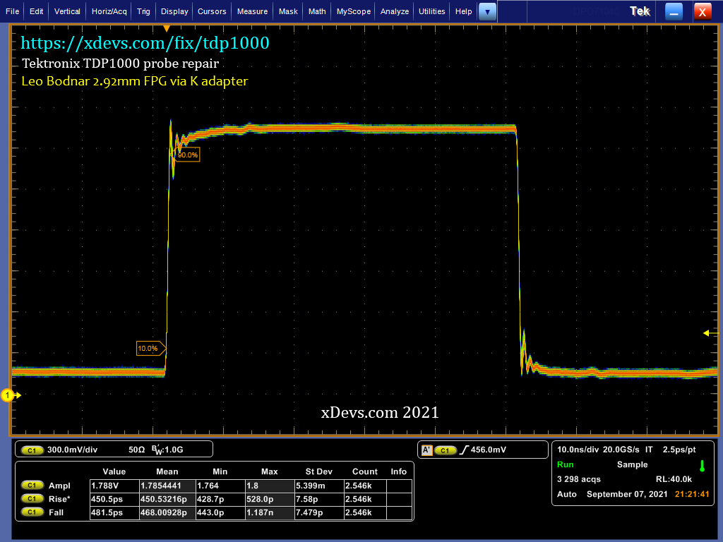
Image : Examination of rise/fall fourth dimension with excellent Leo Bodnar's 2.92mm fast pulse generator (<40ps edges)
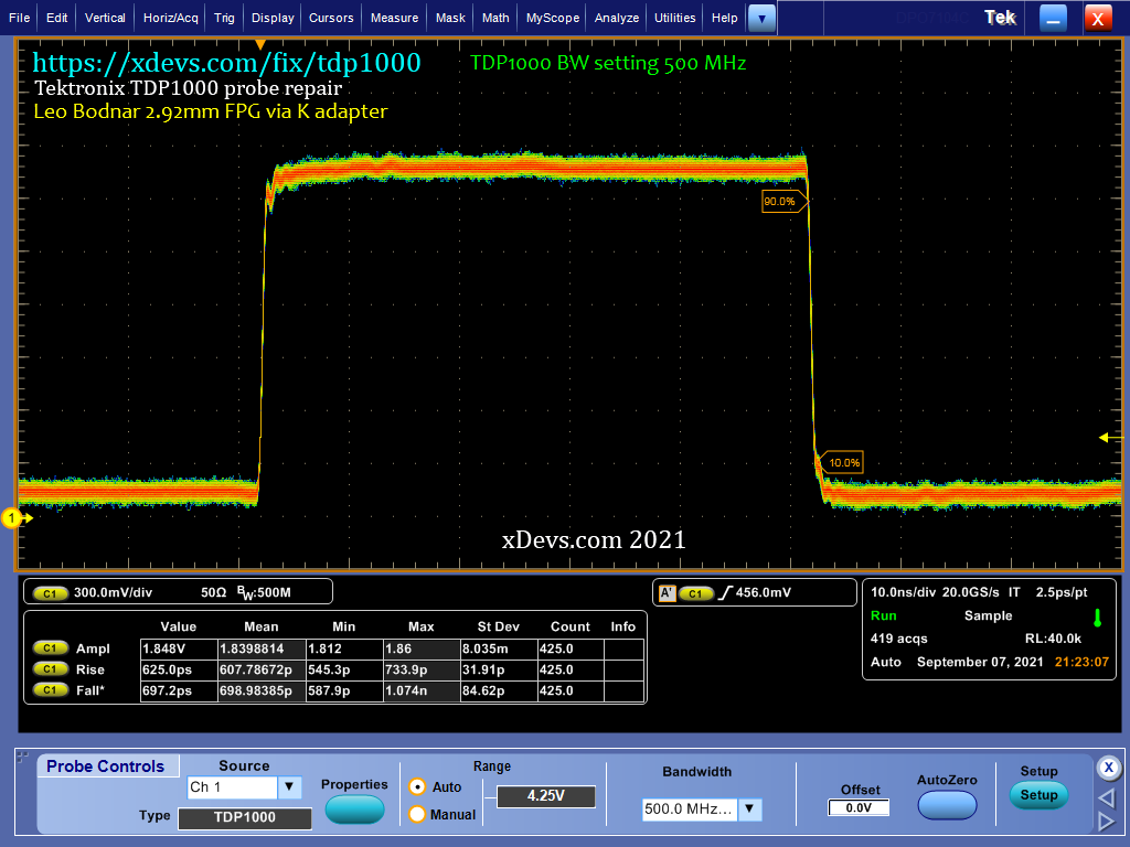
Image : Examination of rise/fall time, limited to 500MHz BW
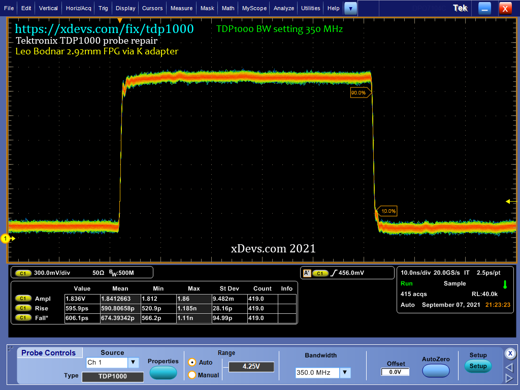
Paradigm : Test of rise/fall fourth dimension, express to 350MHz BW
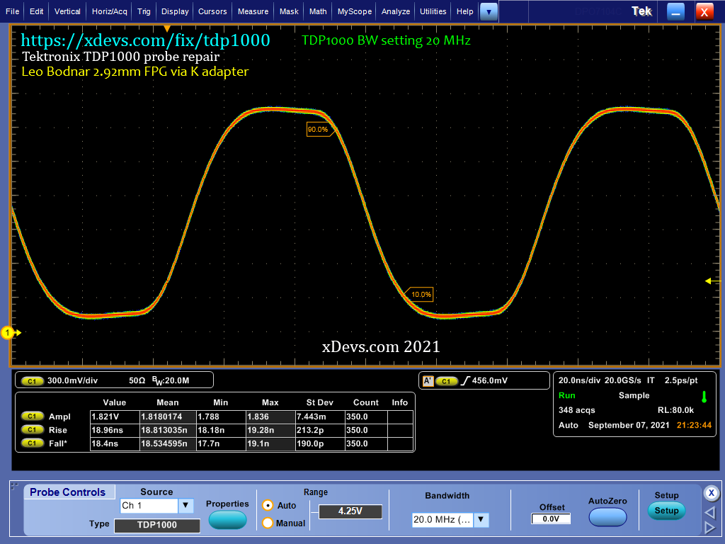
Image : Test of rise/fall fourth dimension, limited to 20MHz BW
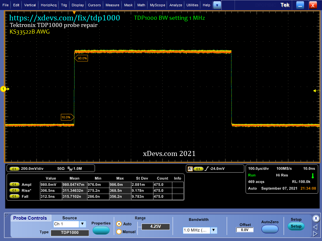
Epitome : Test of ascension/fall time with Keysight 33522B AWG, limited to 1MHz BW
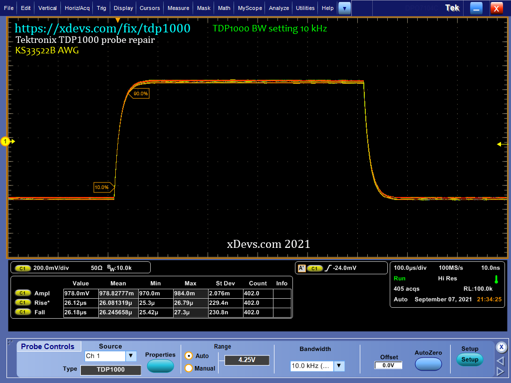
Image : Test of rising/fall time with Keysight 33522B AWG, limited to ten kHz BW
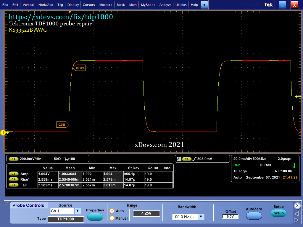
Image : Examination of rise/fall fourth dimension with Keysight 33522B AWG, limited to 100 Hz BW
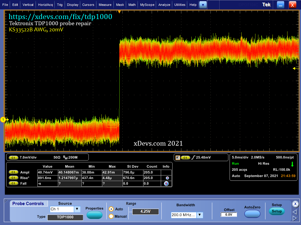
Image : Exam of rise/fall time with Keysight 33522B AWG, 20mV signal, express to 200 MHz BW
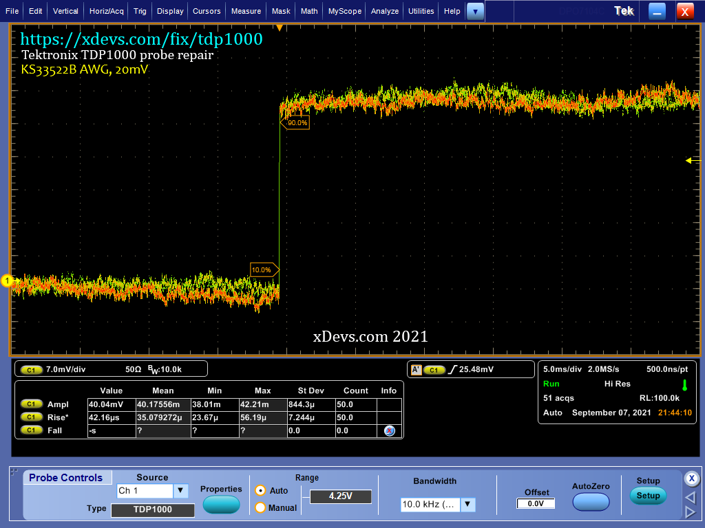
Epitome : Test of rise/autumn fourth dimension with Keysight 33522B AWG, 20mV point, limited to ten kHz BW
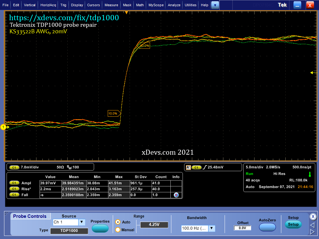
Image : Exam of rise/autumn time with Keysight 33522B AWG, 20mV betoken, limited to 100 Hz BW

Image : Exam of rise/fall time with Keysight 33522B AWG, 9.98V bespeak, limited to one MHz BW

Epitome : Examination of rise/fall fourth dimension with Keysight 33522B AWG, nine.98V signal, express to twenty MHz BW
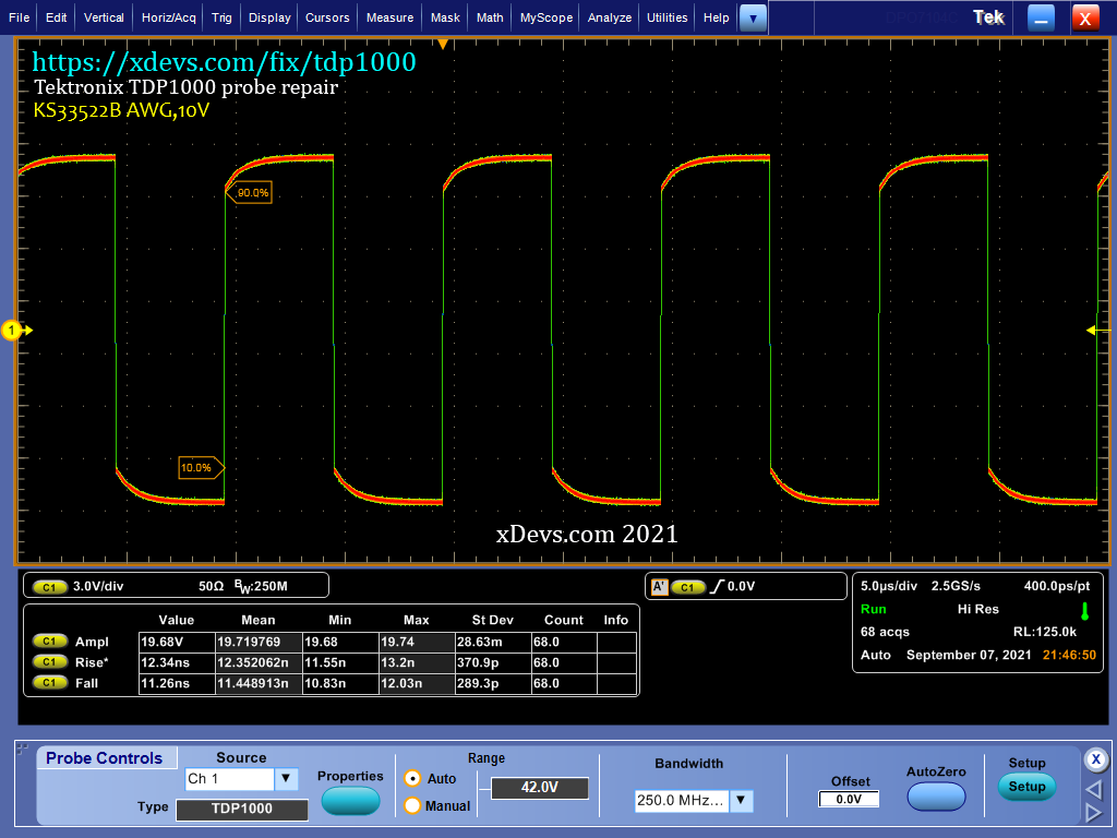
Paradigm : Exam of rise/fall fourth dimension with Keysight 33522B AWG, nine.98V signal, limited to 250 MHz BW

Paradigm : Test of rise/fall time with Keysight 33522B AWG, 9.98V bespeak, unlimited, 1 GHz BW
Benchmarks with Fluke 5720A calibrator
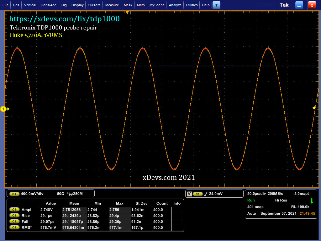
Prototype : Amplitude verification one V RMS 10kHz sine
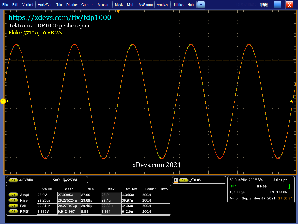
Prototype : Aamplitude verification 10 V RMS 10kHz sine
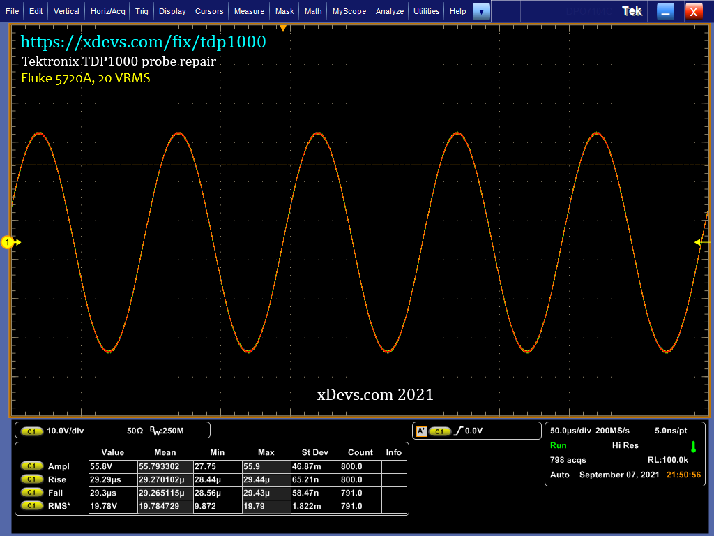
Paradigm : Amplitude verification xx Five RMS 10kHz sine
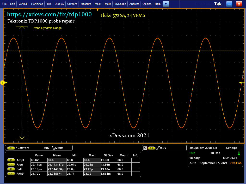
Image : Amplitude verification 24 V RMS 10kHz sine
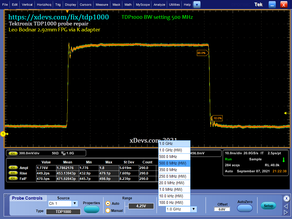
Epitome : All bachelor bandwidth limit settings on Tektronix DPO7104C with TDP1000 probe
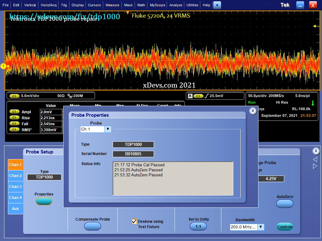
Image : Autozero and calibration exam results

How To Repair Broken Oscilloscope Probe,
Source: https://xdevs.com/fix/tdp1000/
Posted by: colemanwimeved.blogspot.com
0 Response to "How To Repair Broken Oscilloscope Probe"
Post a Comment